|
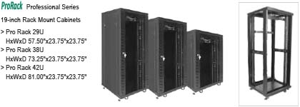
19-inch Rack Mount Cabinet
Professional Series 29U, 38U, and 42U
RMC-Pro-xxx
offers solutions for
custom installers & custom system integrators with a full line of
multi-use Professional Racks that deliver extraordinary capabilities in
construction and performance: elegant yet secure lockable, solid steel
construction; thermal system; power control; and a robust caster system.
These space saving and sturdy racks offer locking custom-designed,
see-through, vented tempered front and fully vented rear doors and
removable sides, which provide quick access to all your Audio/Visual,
Servers, and Network equipment. The rack’s top-mounted,
thermal-controlled dual fans and ventilation construction efficiently
remove heat produced from your enclosed equipment. The internal numbered
mounting rails are depth-adjustable to fit virtually any piece of 19"
equipment. And, in addition to all the included equipment that are
options on most other racks, also has a full line-up of optional
accessories like rack blanks, extra A/C power distribution strips,
standard and/or vented fixed shelving, and sliding (pull out) shelving.
Quick and easy
assembly - Four easy steps
Easy Access:
Removable sides and
reversible front and rear doors
Power Access:
1U 6 outlet Power
Distribution Strip with protected on/off switch
Universal Mounting:
Numbered solid
steel adjustable mounting rails
Cooling:
1U Digital Thermal
Controller and top loaded dual 5" Cooling Fans
Ventilation:
Custom vented tempered
glass door and fully vented rear door
Cable Management:
Removable cable
plates in rack’s top & base, plus space between rails & door for 2"
x 2" PVC cable management molding
Safety:
Locking vented tempered
glass front & vented rear doors, adjustable feet on all four
corners, and heavy duty locking removable caster system (six screws)
Safety
Warning:
- These Professional Series Racks are intended for use only
within the maximum weights indicated. See apparatus instructions.
Use with products heavier than the maximum weights indicated may
result in instability, causing possible injury.
- Do not climb on, rock, shake, stand on, or tilt your
Professional Series Racks.
- Only someone with good mechanical aptitude, who has experience
with basic building construction, and who fully understands this
manual, should install this product.
- Safety gear and proper tools must be used. A minimum of two
people should be required for this installation. Failure to use
safety gear can result in property damage, serious injury or death.
- This product contains small items that could be a choking hazard
if swallowed. Keep these items away from young children.
- Never exceed the Maximum Load Capacity.
- Due to the height and weights of the Professional Series Racks
do not move by yourself assistance is required. Always use an
assistant or mechanical lifting equipment to safely lift and
position equipment.
- Tighten screws firmly, but do not over-tighten. Over-tightening
can damage the items, greatly reducing their holding power
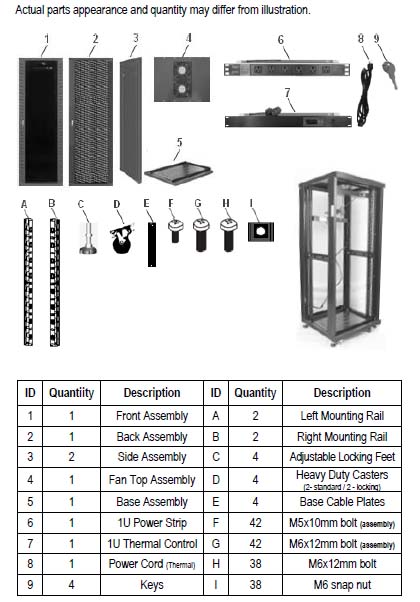
Parts List:
Features:
The high-performance Professional Series Racks have many benefits
and features that enable it to perform in a superior manner. Among those
benefits and features you will find:
- Quick and easy to assemble design allows for flat shipment
- 1U Digital Thermal Controller (LCD display menu) and top loaded
dual 5" Cooling Fans
- 1U 6 outlet Power Distribution Strip with protected on/off
switch and long ground power cord
- Adjustable numbered (EIA standards) mounting rails to fit
virtually any piece of 19" equipment
- Robust locking (2) six screw heavy duty caster system
- Four adjustable (one in each of the four (4) corners of the
base) heavy duty locking feet
- Removable Cable Knockouts on rack’s top and bottom
- Heavy-gauge steel tops and bottoms, seamless steel sides, and
rails
- Load capacity 29U–up to 650 lbs (295Kg) / 38U–up to 700 lbs
(318Kg) / 42U–up to 780 lbs (354Kg)
- Locking, removable, and reversible custom designed vented
tempered glass front door
- Locking, removable, and reversible fully vented rear door
- Heavy duty and durable black textured powder coat finish
- Cable channel molding option between rails and doors for 2" x 2"
PVC" cable management
- 19" equipment width rail size (EIA standard labeling) for the
29U, 38U, and 42U racks
- 29U Rack Dimensions: (H x W x D) 57.50" x 23.75" x 23.75"
(1,460.5 x 603.3 x 603.3mm)
- 38U Rack Dimensions: (H x W x D) 73.25" x 23.75" x 23.75"
(1,860.5 x 603.3 x 603.3mm)
- 42U Rack Dimensions: (H x W x D) 81.00" x 23.75" x 23.75"
(2,057.4 x 603.3 x 603.3mm)
Package Contents:
Before attempting to use these Professional Series Racks, please
check the packaging and make sure the following items are contained in
the shipping carton: (Total of 3 cartons)
- Front, back, and two
(2) side assemblies Top assembly with dual fans
- Two (2) left and two
(2) right mounting rails Base assembly
- 1U digital thermal
controller Four (4) base cable plates
- 1U 6 outlet power
distribution strip Power cord for PDU strip
- Adjustable locking
feet – four (4) Four (4) locking casters
- User's Manual Keys
–two (2) sets of two (2)
- 42 - M5x10mm bolts for
assembly 42 - M6x12mm bolts for assembly
- 38 - M6x12mm snap nut
for mounting rails 38 - M6x12mm bolts for mounting rails
IMPORTANT: For optimum performance and safety, please read these
instructions carefully before assembling, operating, or adjusting this
product. Please keep this manual for future reference. If you do not
understand correct installation instructions, please consult your
regular installation specialist
Installation Guide:
We are not responsible for any personal injury or product damage due
to mishandling, incorrect mounting, incorrect assembly, or incorrect use
of this product
CAUTION: Professional Series Racks are intended only with the
maximum weights indicated. See apparatus instructions. Use with products
heavier than the maximum weights indicated may result in instability,
causing possible injury.
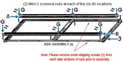
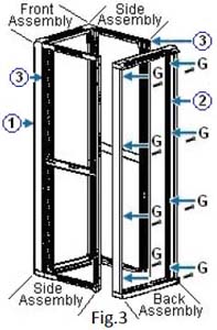
Step 1: Unpacking Carton 2 of 3, removing transit parts, and
side assemblies. (Two (2) Side Assemblies, (2) Left & (2) Right
Mounting Rails)
- Remove the small mini shipping screws (2) opposite of side
door releases on both the left & right side of side rack
assembly (3) to remove side panels to start rack assembly.
- Installing Left (A) and Right (B) Mounting Rails on Left and
Right Side Assembly
- Using M6x12 screws (G) (six (6) per rail) and M6 snap nuts
(I) (six (6) per rail) attach the left (A) and right (B)
mounting rails to Side Assemblies (3) as shown below
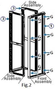
Step 2: Unpacking Carton 1 of 3 and assembly Front & Rear
Assembly to sides.
- Using eight (8) M6x12 screws (G) attach the Front Assembly
(1) as unpacked from carton 1 of 3 and attach to the Left (A)
and Right (B) assemblies as shown in Figure 2.
- Installing the Back Assembly (2) to Left (3), Right (3), &
Front (1) Assemblies
Using eight (8) M6x12 screws (G) attach the Back Assembly
(2) as unpacked from carton 1 of 3 and attach to the left
and right assemblies (3) as shown in Figure 3.
IMPORTANT: Do not force the bolt into the hole, which may damage
equipment and injure of person.
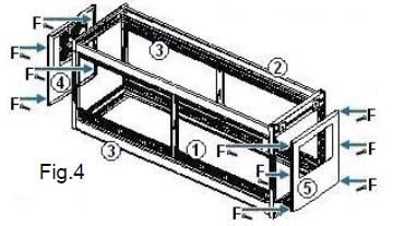
Step 3: Unpacking Carton 3 of 3 and assemble Top & Base Assembly
to rack.
Installing the Top with dual fans and Base Assemblies,
Casters, Legs, and Base Cable Plates (as needed) to rack
assembly.
- Using six (6) M5x10 screws (F) attach the Top
Assembly with dual fans (4) as unpacked from carton 1
of 3 and attach to Rack Assembly as shown in Figure 4.
- Using four (4) M5x10 screws (F) attach the Base
Assembly (5) as unpacked from carton 1 of 3 and
attach to Rack Assembly as shown in Figure 4.
- Using six (6) M5x10 screws (F) (six per caster)
attach two (2) Locking Casters (D) onto the bottom
Front Assembly (1) and two (2) Standard Casters
(D) onto the bottom Back Assembly (2) as shown in
Figure 5a.
- Using a wrench attach two (2) of the Adjustable Locking
Feet (C) onto the bottom Front Assembly (1)
the bottom Back Assembly (2) as shown in Figure 5a.
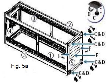
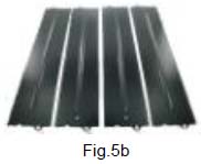
Installing the four (4) (as needed) Base Cable Plates
(E) to the Rack Assemblies
- Stand up the completed rack assemblies. Using two (2)
M5x10 screws (F) for each of the (as needed) Base
Cable Plates (E) (fig.5b) attach each to the top side
of Base Assembly (5) as shown in Figure 5a.
CAUTION: Do to the height and weights of the
Professional Series Racks do not move and/or stand up by
yourself assistance is required. Always use an assistant or
mechanical lifting equipment to safely lift and position
equipment.
Step 4: Attaching the doors and panels to the Rack Assemblies
- Attach the Custom Vented Tempered Glass Door (1),
the Vented Back Door (2), and the left & right Side
Panels (3) to the completed rack assemblies as shown
in Figure 6.
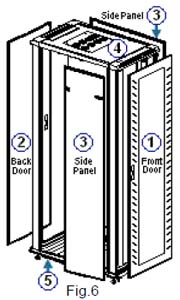
Installing & Adjusting the Front (1) & Back (2) Doors.
- 1) The Front Door (1) and the Back Door (2)
are removable at any time. Just pull down on the top tab
while holding the door. The top of the door will then fall
out of place, then pull up on the bottom tab and lift the
door out of the frame.
- 2) There may be times when the door may need to open in
the other direction. The door’s opening direction can be
changed. Remove the door and turn it so that the handle is
on the other side. Insert the tabs into the holes and close
the door.
Operation and Adjustment
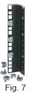
- The Professional Series have two (2) types of (A&B)
mounting rails one set with square mounting holes and one with 10-32
pre - threaded holes. The mounting rails (A&B) are labeled in
EIA standard rack space increments allowing for easy equipment
alignment.
a) Insert the supplied snap nuts (I) by pressing on either
side of the nut, then insert the clamp side into the square hole,
and release into the four (4) mounting rails (A&B) where the
equipment is to be mounted. When completed screw down the equipment
with M6x12mm bolts (H).
b) If the equipment has mounting with hooks, just hook the
bracket into position for any equipment that has mounting brackets
with hooks. c) The mounting rails (A&B) with pre-threaded
10-32 holes just screw equipment directly into desired position.
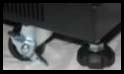
- The Professional Series Racks are equipped with locking
heavy duty casters (D) to easily move the rack. There are
four (4) adjustable locking feet (C) on the base of the rack,
use a wrench to adjust the feet until the legs are lowered enough
that the wheels are slightly off the ground and lock with nut to
base. Also they ensure that the rack does not tip forward when a
heavy drawer is pulled out. (CAUTION - feet may damage flooring if
rack is moved when loaded with equipment)
- Determine the type of optional shelves - Fixed or Sliding
a) Fixed Shelves - secured to the mounting rails (A&B) using
supplied M6x12mm bolts (H) & M6 snap nuts (I).
Short shelves use M6x12mm bolts (H) to attach into place
to the front mounting rails (A&B) of the rack.
Deeper shelves determine the desired height that you want to
install the shelf at, then slide the M6 snap nuts (I) into the
desired location so that they line up with the holes in the shelf
and fasten the shelf with the provided M6x12mm bolts (H) and M6 snap
nuts (I) to the front of the mounting rails (A&B).
b) Sliding Shelves - Determine the desired height to install the
shelf then slide the M6 snap nuts (I) to the desired location
so that they line up with the holes on the mounting rails (A&B)
use M6x12mm bolts
(H).
CAUTION: To
avoid damage to your components due to overheating, ensure that
there is adequate space between each unit for proper airflow. It is
important to maintain an operating temperature inside of the rack
that does not exceed 104°F (40°C).
Attach the 1U Power Strip (6) at desired location using
supplied M6x12mm bolts (H) and M6 snap nuts (I). Plug
power strip’s A/C cord into A/C outlet.
Attach the 1U Thermal Control unit (7) at desired
location using supplied M6x12mm bolts (H) and M6 snap nuts
(I). Connect the thermal power cord (8). Plug A/C cord
from dual fans in Fan Top Assembly (4). Locate the thermal
control unit’s thermal sensor at desired location. See Thermal
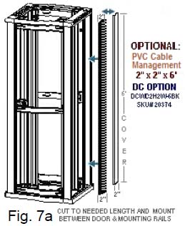
The Professional Series Racks are designed to accommodate
other optional accessories like 2" x 2" PVC cable management molding
between the door frames (1&2) and the racks mounting rails
(A&B) as shown in Figure 7a.
IMPORTANT: Do not force the bolt into the hole, which may
damage equipment and injure a person. Do not use electric drill to
fasten any bolts
|